Hurricane-tracking satellites can also keep tabs on harmful microplastics in the ocean

The Cyclone Global Navigation Satellite System spacecraft

The Cyclone Global Navigation Satellite System spacecraft were designed to track hurricanes but they can also monitor microplastics in the oceans. (Image credit: NASA)

A satellite system designed to track hurricanes can reveal where damaging microplastics accumulate in the ocean. A new study now reveals why.

In 2021, researchers from the University of Michigan and Southwest Research Institute found that spacecraft from the Cyclone Global Navigation Satellite System can distinguish areas in the ocean with higher concentrations of microplastics.

From their orbit some 333 miles (536 kilometers) above Earth, these satellites are able to see odd patches in the ocean with smaller and fewer waves, which were found to be areas with high concentrations of microplastics on the surface. In the new study, the researchers have now revealed what exactly is happening in the microplastic-laden water, and they hope the results will make this new satellite monitoring method more reliable.

Microplastics are a huge environmental problem. Less than 5 millimeters across, these minuscule fragments of plastic waste are polluting the entire planet, including the bodies of humans and animals on all continents and in the oceans. Microplastics have been found in drinking water as well as in the food we eat. In the world’s oceans, microplastics are particularly harmful. According to the University of Plymouth(opens in new tab) in the U.K., there are trillions of microplastic particles polluting the marine environments and they are being swallowed up by all kinds of marine creatures from the tiniest plankton to giant whales. These tiny pieces of rubbish are particularly hard to clean up due to their small size, and up until recently were also hard to track, as scientists had to rely on patchy eye-witness accounts.

The new satellite tracking method could improve microplastic monitoring, which in turn could make clean-up efforts easier.

In the new study, researchers from the University of Michigan wanted to test why exactly it is that water thickly polluted with microplastics forms smaller waves. They experimented in a laboratory, creating artificial waves in a small pool. They found that the reason for this reduced wave size in the polluted water is not due to the microplastics alone, and instead is also caused by the presence of surfactants, oily chemicals that these plastics are frequently infused with to alter their properties.

Researchers tested about water

Researchers tested how microplastics affect the ability of water to form waves. (Image credit: Robert Coelius, Michigan Engineering)

“We can see the relationship between surface roughness and the presence of microplastics and surfactants,” Yulin Pan, a naval architecture and marine engineering assistant professor at the University of Michigan and corresponding author on the paper, said in a statement(opens in new tab). “The goal now is to understand the precise relationship between the three variables.”

The researchers want to develop a model that would allow them to not only monitor microplastics from space but also to predict the motion of plastic-polluted water in the ocean.

The study(opens in new tab) was published on Feb. 8 in the journal Scientific Reports.

Follow Tereza Pultarova on Twitter @TerezaPultarova. Follow us on Twitter @Spacedotcom and on Facebook.

Join our Space Forums to keep talking space on the latest missions, night sky, and more! And if you have a news tip, correction, or comment, let us know at: [email protected].

Chromium-nickel alloy 600 and its processing technology

Alloy 600 (UNSN0660) is an alloy with nickel as the main component and resistance to various corrosion conditions. Alloy 600 (UNSN0660) can be used in low-temperature and high-temperature environments of 20000F (10930C). It has no magnetism and can be welded for corrosion resistance. Its nickel alloy content is high, and it has strong corrosion resistance and good resistance to chloride stress corrosion cracking. Chromium makes it suitable for low oxidation environments.

General characteristics

Alloy 600 (UNS designated N0660) is a chrome-nickel alloy, which is designed for environments ranging from low temperatures to 2000 degrees Fahrenheit (1093 degrees Celsius). The alloy is non-magnetic and easy to weld. Alloy 600 is used in various anti-corrosion fields. Its high nickel content shows a certain degree of corrosion resistance in environments with reduced corrosion degree, while chromium in the alloy has corrosion resistance in a weak oxidation environment. The high nickel content in the alloy has special resistance to chloride corrosion fission.

Application field:

① Chemical and food processing equipment

② Paper mill and alkali digester

③ Heat exchanger

④ Heat treatment silencer and evaporator.

Heat treatment:

Alloy 600 will not harden during heat treatment. The hardness of the alloy can only be enhanced by cold treatment. After cold working, the alloy is annealed to soften the material. Softening needs to be carried out from the initial temperature of 1600 degrees Fahrenheit (871 degrees Celsius) to 2100 degrees Fahrenheit (1149 degrees Celsius). When the temperature rises to 1800 degrees Fahrenheit (982 degrees Celsius) or higher, the particles will grow rapidly. However, if the material is softened at 1900 degrees Fahrenheit (1038 degrees Celsius) in a very short time, the particles can be prevented from getting too large. Slow cooling and quenching can keep the hardness of alloy 600 approximately the same.

Processing:

Alloy 600 exhibits good cold-forming properties, which is related to the Ni-Cr stainless steel it contains. Its high nickel content prevents its transformation from austenitic steel to martensitic steel, which will occur when 301 stainless steel alloy and 304 stainless steel alloy are cold formed. Compared with 301 alloy and 304 alloys, the effective hardening rate of 600 alloys is lower, and it can be used for rolling forming by various methods, but a large amount of deformation will occur between annealing and annealing.

If high*temperature annealing is used, alloy 600 produces relatively large particles to obtain the characteristics brought by the temperature rise, and the surface is formed in the maximum range to form obvious waviness, which is called “orange peel”. This phenomenon is caused by large particles, which are generally considered harmful to the material properties.

Welding:

The standard resistance welding and fusion welding of stainless steel can be used for alloy 600. Electrodes and wires for welding alloy 600 and other materials can be found on the market. Because this alloy will produce oxides with strong adhesion, inert gas protection should be reasonably used.

What is the material of 4142 round bar 4142 steel plate?

Introduction to 4142 alloy steel:
4142 steel is an ultra-high-strength steel with high strength and toughness, good hardenability, no obvious temper brittleness, high fatigue limit, multiple impact resistance after quenching and tempering, and good low-temperature impact toughness. This steel is suitable for manufacturing large and medium-sized plastic molds that require a certain strength and toughness. Usually, surface quenching after quenching and tempering is used as a heat treatment solution.

4142 round rod performance

4142 alloy steel chemical composition:
Carbon C: 0.40~0.45%
Silicon Si: 0.15~0.35%
Manganese Mn: 0.75~1.00%
Sulfur S: ≤0.040%
Phosphorus P: ≤0.035%
Chromium Cr: 0.80~1.10%
Molybdenum Mo: 0.15~0.25%

Italian customer successfully placed an order

Product name: Oxygen-free copper rod

Customer country: Italy

60mm in diameter, 720mm in length, one single weight of 18.5kg

Material: C10700

Product packaging

17-7PH hardening (RH950) low temperature quenching + aging

17-7PH or Type 631 (UNS S17700) is a chromium-nickel aluminum precipitation hardening stainless steel used for spring applications in numerous industries.

7-7 Precipitation hardening alloys can be formed in the soft austenitic state and hardened to high strength levels by low-temperature heat treatment. The low temperature allows for minimal deformation compared to conventional quench and temper hardening processes. In the soft austenitic annealed condition, 17-7 is highly formable and is ideal for operations such as drawing, bending, and end forming. 17-7 is readily weldable in both the annealed and heat-treated conditions.

Element:
Carbon: 0.09 max

Manganese: 1.00 max

Phosphorus: 0.040 max

Sulfur: 0.030 max

Silicon: 1.00 max

Chrome: 16.00 – 18.00

Nickel: 6.50 – 7.75

Aluminum: 0.75 – 1.50

Iron: Balanced

Physical properties:
Melting point: 2550 – 2640°F (1400 – 1450°C)

Density: 0.282 lb/in3 / 7.8 g/cm3

Tensile Modulus of Elasticity (RH 950 and TH 1050): 29.6 X 10 6 psi / 204 GPA

Mechanical behavior:
Condition: annealed
Tensile Strength Minimum (psi): 130,000

Yield Strength Min. 0.2% Offset (psi): 40,000

2″ Elongation Typical: 35%

Hardness: Rockwell B85

Condition: hardened + aged (TH1050)
Typical Tensile Strength (psi): 200,000

Yield Strength Typical 2% Shift (psi): 185,000

% elongation at 2″: 9%

Hardness: Rockwell C40

Condition: hardened, low temperature quenching + aging (RH950)

Typical Tensile Strength (psi): 235,000

Yield Strength Typical 2% excursion (psi): 220,000

% elongation at 2″: 6%

Hardness: Rockwell C48

Condition: Cold Rolled/Worked + Aged (CH900)
Typical Tensile Strength (psi): 265,000

Yield Strength Typical 2% excursion (psi): 260,000

% elongation at 2″: 2%

Hardness: Rockwell C49

heat treatment:
17-7 requires three basic steps in heat treatment:

Austenitic conditioning.

Cooling transforms austenite to martensite

Precipitation hardening to TH 1050 or RH 950 conditions

Alternatively, to obtain the highest mechanical properties from the alloy, the condition A material is transformed to martensite by cold reduction to condition C in the rolling mill. Hardening to condition CH 900 is accomplished by a single low-temperature aging heat treatment.

American scientists discover the highest toughness alloy still has ultra-high performance in extreme cold

The Berkeley National Laboratory in the United States has discovered that an alloy composed of chromium, cobalt, and nickel is the hardest material with the most fracture-resistant properties. The picture shows the nanoscale fracture path and accompanying crystal structure deformation of CrCoNi alloy during the 20 Kelvin stress test. Cracks expand from left to right

With the increasing demand for human exploration of space and extreme regions, people began to look for metal materials that can be used at low temperatures. The National Laboratory of the United States discovered an alloy composed of chromium, cobalt, and nickel, which can maintain extremely high toughness at extremely low temperatures and is currently the toughest alloy in the world.

Lawrence Berkeley National Laboratory and Oak Ridge National Laboratory in the United States jointly wrote the results of this experiment into a paper, which will be published in the journal Science in December 2022. This research was supported by the U.S. Department of Energy’s Office of Science.

Scientists study alloy metals made of “chromium, cobalt, and nickel” and “chromium, manganese, iron, cobalt, and nickel” in equal proportions, and test their fracture toughness values. It is observed that “chromium manganese iron cobalt nickel” and “chromium fracture toughness values of “cobalt-nickel” alloy at minus 253.15°C are 262 and 459 MPa-square root meters, respectively.

In addition, it was found through experiments that the “Chromium-Cobalt-Nickel” alloy exhibited a crack growth toughness exceeding 540 MPa-square root meters after a stable crack of 2.25 mm. The above values represent that the alloy has the highest toughness in the world. Scientists also found that the deformation of the metal at low temperatures and the deformation structure at high temperatures have completely different results.

This alloy is not only extremely ductile, but also extremely malleable, and at the same time very strong (almost permanently resistant to deformation). In addition, the alloy has a very special property, its strength and ductility will increase as the temperature decreases, which is the opposite of the properties of most materials in the world.

An alloy made of chromium, cobalt, and nickel, which belongs to the type of high-entropy alloy, which is different from other general alloys. The difference is that other alloys will consist of a high proportion of one metal (for example, iron, gold, silver, or copper, etc.) and small amounts of other elements or metals (for example, stainless steel, 18K gold, etc.), but HEA type alloys, It is made by mixing each element in almost equal proportions.

These alloys, in which equal amounts of each element are mixed, appear to endow the material with very high “strength” and “ductility” combined into the “toughness” of metal when stressed.

They found that these alloys did not have a complex microstructure when pressure was applied at room temperature, but when pressure was applied at extremely low temperatures, the microstructure began to become complex. The crystallization in the alloy will change from round grains to strips, with a strong tendency of plane deformation, and finally, form a bunch of criss-cross deformation bands. Therefore, it is speculated that these changes allow the alloy metal to enhance its toughness.

“Originally the metal atoms in this alloy were smooth and simple grains, but at low-temperature pressure, they appear When it deforms, it starts to have a lot of obstacles inside, which gives it a fracture toughness value that far exceeds that of most materials.”

Andrew Jr., director of the lab’s Center for Electron Microscopy, added: “When a metal deforms, its structure becomes very complex, and this transformation helps explain why it exhibits this resistance to fracture.”

In addition, Professor Rich also said: “This material has a fracture toughness value as high as 500 MPa-square root meters at the temperature of liquid helium (-253.15 ° C).”

Professor Rich explained: “If in the same unit, the fracture toughness value of a piece of silicon is 1 M MPa-square root meter, the fracture toughness value of the aluminum alloy fuselage used in passenger planes is 35 MPa-square root meters, and the best steel fractures With a toughness value of 100 MPa-square root meters, the value exhibited by this alloy is quite astonishing.”

However, Professor Ritchie said that while the current development is exciting, it is still too early to be practical. “We need more time to better understand the properties of this material so that we can put it into practical applications in the future, and avoid accidents that people don’t want to see when people use it.”

The newsroom reported that George and Ritchie, professors of engineering at Oak Ridge National Laboratory, began researching chromium-cobalt-nickel alloys a decade ago, combining the metal with manganese and iron-containing chromium-manganese-iron-cobalt nickel alloy.

When they put the material at the temperature of liquid nitrogen (-196 °C) to observe the changes in the metal, they found that the alloy had impressive toughness and strength. In order to test various samples at this cold temperature, it took them 10 years to find all kinds of personnel and tools, and finally came to the experimental results.

Welding method of martensitic stainless steel and duplex stainless steel

1. What are martensitic stainless steel and duplex stainless steel?

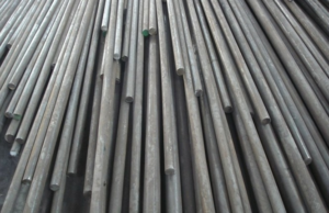
The microstructure is martensitic at room temperature, and its mechanical properties can be adjusted by heat treatment. In layman’s terms, it is a type of hardenable stainless steel. The steel grades belonging to martensitic stainless steel include 1Cr13, 2Cr13, 3Cr13, 4Cr13, 3Cr13Mo, 1Cr17Ni2, 2Cr13Ni2, 9Cr18, 9Cr18MoV, etc.

2. Commonly used welding methods

Welding Martensitic stainless steel can be welded by various arc welding methods. At present, electrode arc welding is still the main method, but the use of carbon dioxide gas-shielded welding or argon and carbon dioxide mixed gas-shielded welding can greatly reduce the hydrogen content in the weld, thereby reducing the sensitivity of the weld to cold cracking.

3. Common welding materials

(1) Cr13 martensitic stainless steel electrodes and wires

Usually, when the weld has high strength requirements, the use of a Cr13 martensitic stainless steel electrode and wire can make the chemical composition of the weld metal similar to that of the base metal, but the weld has a greater tendency to cold crack.

Precautions:

a. Preheating before welding is required, and the preheating temperature should not exceed 450°C to prevent embrittlement at 475°C. After welding, heat treatment is carried out. The post-weld heat treatment is to cool to 150-200 ° C, keep it warm for 2 hours so that all parts of the austenite are transformed into martensite, and then immediately perform high-temperature tempering, heating to 730-790 ° C, and then holding time is every 1mm plate thickness is 10min, but not less than 2h, and finally air-cooled.

b. In order to prevent cracks, the content of S and P in electrodes and wires should be less than 0.015%, and the content of Si should not be greater than 0.3%. The increase in Si content promotes the formation of coarse primary ferrite, resulting in a decrease in the plasticity of the joint. The carbon content should generally be lower than that of the base metal, which can reduce the hardenability.

(2) Cr-Ni austenitic stainless steel electrodes and wires

The Cr-Ni austenitic steel-type weld metal has good plasticity, which can relieve the stress generated during martensitic transformation in the heat-affected zone. In addition, the Cr-Ni austenitic stainless steel weld has a high solubility for hydrogen, which can reduce the diffusion of hydrogen from the weld metal to the heat-affected zone and effectively prevent cold cracks, so preheating is not required. However, the strength of the weld is low and cannot be improved by post-weld heat treatment.

4. Common welding problems

(1) welding cold crack

Due to the high chromium content of martensitic stainless steel, its hardenability is greatly improved. Regardless of the original state before welding, welding will always produce a martensite structure in the area near the seam. As the hardening tendency increases, the joint is also more sensitive to cold cracking, especially in the presence of hydrogen, and martensitic stainless steel will also produce more dangerous hydrogen-induced delayed cracking.

measure:

1) The cooling rate can be slowed down by using a welding current with a large line energy and a large welding current;

2) For different steel types, the temperature between layers is different, generally not lower than the preheating temperature;

3) Slowly cool to 150-200°C after welding, and perform post-weld heat treatment to eliminate welding residual stress, remove diffused hydrogen in the joint, and improve the structure and performance of the joint.

(2) Embrittlement of the heat-affected zone

Martensitic stainless steel, especially martensitic stainless steel with higher ferrite-forming elements, has a greater tendency for grain growth. When the cooling rate is small, coarse ferrite and carbides are easily produced in the welding heat-affected zone; when the cooling rate is high, the heat-affected zone will harden and form coarse martensite. These coarse structures reduce the plasticity and toughness of the welded heat-affected zone of martensitic stainless steel and cause embrittlement.

measure:

1) Control a reasonable cooling rate;

2) Choose the preheating temperature reasonably, and the preheating temperature should not exceed 450°C, otherwise, the joints may be embrittled at 475°C if they are exposed to high temperatures for a long time;

3) Reasonable selection of welding materials to adjust the composition of the weld to avoid the generation of coarse ferrite in the weld as much as possible.

5. Welding process

1) Preheating before welding

Preheating before welding is the main technological measure to prevent cold cracks. When the mass fraction of C is 0.1%~0.2%, the preheating temperature is 200~260°C, and it can be preheated to 400~450°C for high rigidity weldments.

2) Cooling after welding

After welding, the weldment should not be tempered directly from the welding temperature, because the austenite may not be completely transformed during the welding process. If the temperature is raised and tempered immediately after welding, carbides will precipitate along the austenite grain boundary and austenite Transformation to pearlite produces a coarse-grained structure that seriously reduces toughness. Therefore, the weldment should be cooled before tempering, so that the austenite in the weld and heat-affected zone is basically decomposed. For weldments with low rigidity, it can be cooled to room temperature and then tempered; for weldments with large thickness, a more complicated process is required; after welding, cool to 100-150°C, keep warm for 0.5-1h, and then heat to tempering temperature.

3) Post-weld heat treatment

The purpose is to reduce the hardness of the weld and heat-affected zone, improve plasticity and toughness, and reduce welding residual stress at the same time. Post-weld heat treatment is divided into tempering and complete annealing. The tempering temperature is 650-750°C, hold for 1 hour, and air-cool; if the weldment needs to be machined after welding, in order to obtain the lowest hardness, complete annealing can be used. The annealing temperature is 830-880°C, and the heat preservation is 2 hours. Then air cool.

4) Selection of welding rod

Electrodes for welding martensitic stainless steel are divided into two categories: chromium stainless steel electrodes and chrome-nickel austenitic stainless steel electrodes. Commonly used chromium stainless steel electrodes are E1-13-16 (G202), and E1-13-15 (G207); commonly used chromium-nickel austenitic stainless steel electrodes are E0-19-10-16 (A102), E0-19-10-15 (A107), E0-18-12Mo2-16 (A202), E0-18-12Mo2-15 (A207), etc.

Welding of duplex stainless steel

1. Weldability of duplex stainless steel

The weldability of duplex stainless steel combines the advantages of austenitic steel and ferritic steel and reduces their respective shortcomings.

(1) The sensitivity to hot cracks is much smaller than that of austenitic steel;

(2) The sensitivity to cold cracks is much smaller than that of general low-alloy high-strength steel;

(3) After the heat-affected zone is cooled, more ferrite is always retained, thereby increasing the corrosion tendency and the susceptibility to hydrogen-induced cracking (brittleness);

(4) Duplex stainless steel welded joints may precipitate δ phase embrittlement. δ phase is an intermetallic compound of Cr and Fe. Its formation temperature ranges from 600 to 1000 ° C. Different steel types have different temperatures for forming the δ phase;

(5) Duplex stainless steel contains 50% ferrite, which also has brittleness at 475°C, but is not as sensitive as ferritic stainless steel;

2. Selection of welding method

TIG welding is the first choice for duplex steel welding, followed by electrode arc welding. When submerged arc welding is used, heat input and interlayer temperature should be strictly controlled, and large dilution rates should be avoided.

Notice:

When using TIG welding, it is advisable to add 1-2% nitrogen to the shielding gas (if N exceeds 2%, it will increase the tendency of pores and the arc is unstable), so that the weld metal absorbs nitrogen (to prevent the surface area of the weld from diffusing loss of nitrogen), which is conducive to stabilizing the austenite phase in the welded joint.

3. Selection of welding consumables

Welding consumables with higher austenite-forming elements (Ni, N, etc.) are selected to promote the transformation of ferrite to austenite in the weld.

2205 steel mostly uses 22.8.3L welding rod or wire, and 2507 steel mostly uses 25.10.4L welding wire or 25.10.4R welding rod.

4. Welding points

(1) Control of welding heat process Welding heat energy, interlayer temperature, preheating, and material thickness will all affect the cooling rate during welding, thereby affecting the structure and performance of the weld and heat-affected zone. In order to obtain the best weld metal properties, it is recommended that the maximum interpass temperature be controlled at 100°C. When heat treatment is required after welding, the interpass temperature may not be limited.

(2) Post-weld heat treatment It is best not to heat-treat duplex stainless steel after welding. When heat treatment is required after welding, the heat treatment method used is water quenching. During heat treatment, the heating should be as fast as possible, and the holding time at the heat treatment temperature is 5 to 30 minutes, which should be sufficient to restore the phase balance. Metal oxidation is very serious during heat treatment, and inert gas protection should be considered.

Orders from Australian customers

We received the customer’s Round Bar copper-nickel (90/10) inquiry in September, and the agreed delivery time is 20 days. Overall, everything is going according to plan.

Unfortunately, the quantity requested by the customer is only 1 of each size. The customer is a careful person and requires samples to be sent first, and the order will be placed after the sample is passed the test. The sample passed the test and passed the test. In October, we were honored to receive the official order from the customer, and the goods were shipped in November. In December, we received the customer’s second order and shipped it.

It is my pleasure to share the specifications and photos of the goods with you:

product order

product diplay

We are very pleased to be able to connect 2 orders! We sincerely thank our customers for their strong support. I hope our future cooperation will be closer. We will wholeheartedly provide you with the most cost-effective product
If you need Round Bar copper-nickel (90/10), Cu90Ni10 Solid Bar, welcome to inquire, we will serve you wholeheartedly! Email: [email protected]


NASA astronauts unfurl 4th roll-out solar array on spacewalk outside space station

Only two more new solar arrays are to be installed after a successful spacewalk.

The International Space Station (ISS) has a fourth new solar array thanks to the work of two NASA astronauts on a seven-hour spacewalk.

Frank Rubio and Josh Cassada, both flight engineers on the space station’s Expedition 68 crew, again ventured outside of the orbiting complex on Thursday (Dec. 22) to install a new ISS Roll-Out Solar Array (iROSA) to augment the station’s power supply. The spacewalk was a near repeat of the extravehicular activity (EVA) that Rubio and Cassada performed almost three weeks ago, but this time focused solely on a power channel located on the station’s port-side truss.

The two astronauts also reversed roles, with Rubio serving as the lead spacewalker (EV-1) for Thursday’s outing. Rubio and Cassada began the spacewalk at 8:19 a.m. EST (1319 GMT), exiting the U.S. Quest airlock and quickly getting to work on their first assigned tasks. As Cassada set up a foot restraint at the end of the station’s Canadarm2 robotic arm, Rubio configured the cables that they would later connect to tie the new array into the station’s 4A power channel.

space station

NASA astronaut Frank Rubio (in the foreground) transitions along the space station as fellow NASA astronaut and Expedition 68 crewmate Josh Cassada moves an International Space Station (ISS) Roll-Out Solar Array (iROSA) on the end of the Canadarm2 robotic arm during a spacewalk on Thursday, Dec. 22, 2022. (Image credit: NASA TV)

The two astronauts then worked together to free the iROSA from the platform on which it was launched and temporarily stowed on the station. Like the array that was installed on Dec. 3, the 4A iROSA was delivered to orbit by a SpaceX CRS-26 Dragon cargo spacecraft, which arrived at the ISS on Nov. 27.

After Rubio freed the last bolt holding the array in place, Cassada, now positioned at the end of the robotic arm, took hold of the assembly to carry it to its installation site. At the controls of the Canadarm2 was NASA astronaut Nicole Mann, with Koichi Wakata of the Japan Aerospace Exploration Agency (JAXA) coordinating her actions with Cassada outside.

“Just a head’s, Koichi,” radioed Cassada during a break between moves, “that last one stopped a little quickly on me. If you see it ramping up on the next one, can you give me a heads-up? That would be awesome.” Although weightless in the microgravity environment of space, the mass of the 750-pound (340-kg) still had significant inertia when being moved.

RELATED STORIES:
— The most memorable spacewalks in history

— The International Space Station: Facts, history, and tracking

— In photos: The amazing spacewalks of Expedition 61

Rubio transitioned along the truss to meet Cassada at the P4 site. The two spacewalkers then unfolded the iROSA from its launch configuration and then secured the array atop a mounting bracket installed on an earlier EVA. Using a power tool specifically designed for astronauts to use on spacewalks, Rubio tightened the four bolts on the right and left sides of the iROSA to hold the assembly open.

After waiting for the space station to be in “eclipse,” or when it was in the shadow of Earth, such that the existing solar array wings were not producing electricity, Rubio and Cassada then integrated the iROSA into the 4A power channel by attaching cables connecting the new array to the station.

A new International Space Station (ISS) Roll-Out Solar Array (iROSA) unfurls in front of the legacy 4A solar array wing, augmenting the power for the orbiting complex. (Image credit: NASA TV)

At that point, all that was left to do was let the iROSA unfurl. With the release of two bolts, the potential energy stored by the rolled-up carbon composite booms caused the array to unroll on its own to its full 63-foot (19-meter) length with no motor needed.

“We can finally run that microwave we’ve wanted to run,” said Cassada, joking about the extra power from the new array.

The whole process took about 10 minutes. Cassada tightened two bolts to stiffen the array and its installation was complete.

The ISS Roll-Out Solar Arrays are being installed in front of, and partially overlaying, slightly-degraded, existing solar panel wings. When used in tandem and once all six iROSAs are in place, the upgraded power system will increase the space station’s electricity supply by 20 to 30 percent.

Cassada and Rubio completed the spacewalk by cleaning up and taking inventory of their tools before reentering the airlock at 3:27 p.m. EST (2027 GMT), seven hours and eight minutes after they began the EVA.

Thursday’s excursion had been scheduled for Wednesday but was delayed a day because the space station needed to be maneuvered away from an approaching piece of Russian rocket debris. It was the third spacewalk for both Rubio and Cassada. They now have logged 21 hours and 24 minutes working the vacuum of space.

The EVA was the 12th for the year, the fourth for Expedition 68, and the 257th since 1998 in support of the assembly and maintenance of the ISS.

Corrosion patterns of stainless steel in industrial water systems

1. Corrosion of cooling water to the stainless steel heat exchanger

Chromium-nickel steel, especially 18Cr-8Ni austenitic stainless steel, is most widely used in the chemical industry due to its high stability in many chemical media and its ability to resist high-temperature gas corrosion. Although stainless steel has a very low overall corrosion rate in various industrial waters, under actual industrial production conditions, accidents of corrosion damage to stainless steel equipment, especially various industrial water coolers, are very frequent.

In industrial water, the pitting corrosion and stress corrosion cracking of stainless steel is caused by chloride ions in the water, so people often hope to find out the critical chloride ion concentration that causes stress corrosion cracking, but due to the factors that cause localized corrosion of stainless steel in the actual operating device It is difficult to determine, so it is often found that the life of two equipment with roughly the same conditions is very different; the same stainless steel has stress corrosion cracking in cooling water with a low concentration of chloride ions (only 10~20mg/L). However, it is safe to use for a long time in seawater with a high concentration of chloride ions. Although the mechanism of stress corrosion cracking has not been fully understood so far, and the boundary conditions for completely avoiding or eliminating stress corrosion cracking cannot be proposed, the statistical analysis of the operation of a large number of industrial equipment and many in-depth laboratory studies have enabled people to understand To the main factors affecting stainless steel pitting corrosion and stress corrosion cracking, put forward some statistical laws, these works are very beneficial to prolong the operating life of stainless steel equipment.

The corrosion resistance of stainless steel often depends on the oxide film existing on the metal surface, and the oxide film can only be formed when there is oxygen, oxidant, or anodic polarization. Once the necessary oxidation conditions are lost, the oxide film will be destroyed, such as in crevices and under deposits. Such damage conditions may occur. In water with fully dissolved oxygen, as long as the water flow rate is not lower than 1.5m/s, no deposits will appear on the surface of the stainless steel, and the integrity of the oxide film can be maintained. Under the actual operating conditions of industrial water, the water flow rate is often lower than 1.5m/s, various solid particles will deposit, microorganisms in the water will cause dirt, and sometimes there will be gaps in the equipment structure, especially in the water. Aggressive chloride ions, result in pitting corrosion and even stress corrosion cracking. Of course, there must be tensile stress in order to produce stress corrosion cracking. In addition, pitting corrosion and stress corrosion cracking are related to chloride concentration, pH value, oxygen concentration, temperature, stress level, cation, and other factors, but the degree of dependence is different.

2. Pitting corrosion and crevice corrosion of stainless steel

Stainless steels immersed in chloride-containing aqueous solutions are prone to pitting and crevice corrosion. When the stainless steel is above the critical pitting potential in the corrosive medium, the active area will be polarized by the anode current due to the existence of a passivation-activation battery, which will intensify the development of pitting corrosion. Once pitting is induced and developed, the chloride ions in the pits will autocatalyze concentration (enrichment). Numerous studies have revealed that the pH value and chloride ion concentration of the solution where pitting and crevice corrosion occur are completely different from the bulk solution. The pH value at the place of occurrence is significantly lowered, and the concentration of chloride ions is highly concentrated. There are literatures that use artificial corrosion pits to study the corrosion of 304L, 316L, and 18Cr15Ni5Mo (at 70°C, 0.5mol/L, NaCl solution), the measurement results of the composition and pH value of the solution in the hole are shown in the table below.

stainless steel material

The concentration of original chloride ions in raw water or circulating water does not have decisive significance on whether pitting corrosion occurs in stainless steel. In the system where pitting occurs, the test results of chloride ions in the pits prove that the concentration of chloride ions is amazing. For example, the cooling water of a factory contains only 50mg/L of Cl-, but the concentration of Cl- in the corrosion pit is as high as 104mg/L. Usually, the Cl-concentration in the corrosion pit is several thousand mg/L, and the CI-concentration in the artificial crevice can reach 105mg/L. This fact also exists in production practice. 1Cr18Nil0Ti steel has pitting corrosion in tap water containing 196mg/L of chloride ions and in river water with low chloride ion concentration, and pitting corrosion occurs under sediments. Once steps are taken to remove the deposit or rust, the problem is avoided. As another example, in a water system with low chloride ion content, austenitic stainless steel was also damaged, and a high concentration of chloride deposition was found at the damaged site. These facts show that despite the large difference in the Cl-concentration of the system, as long as there is sediment, it will eventually produce the same bad results. Although the increase of CI- concentration will negatively shift the pitting corrosion potential of stainless steel, the effect is not obvious under the conditions of normal temperature and low Cl- concentration (<10< span=””>3mg/L).

3. Stress corrosion cracking of stainless steel

In industrial water, the stress corrosion cracking of austenitic stainless steel is induced by pitting corrosion. The influencing parameters of the two are the same, but the critical values required by each are different. As for the effect of stress when stress corrosion cracking occurs, the 18-8 austenitic stainless steel was studied in 0.05mol/L NaCI with the specimen in the occluded area under tension, and it was found that when the specimen was anodically polarized (oV, SCE), The crack is the active area, the tensile stress promotes the rupture of the passivation film, and makes it difficult to repair the film. As a result, the potential here becomes more negative, the pH value drops faster, and the corrosion is more serious.

4. Intergranular corrosion of stainless steel

In most cases, intergranular corrosion of austenitic stainless steels is caused by chromium-depleted regions adjacent to grain boundaries. Stainless steel must have a certain amount of chromium. If the chromium content decreases, its corrosion resistance will deteriorate. When the carbon content is ≥0.02%, in the temperature range of 510~788°C, chromium carbide Cr23C8 or carbon will precipitate at the grain boundary. In this way, chromium will be separated from the solid solution in the form of chromium carbide, which will reduce the chromium content near the grain boundary and form a chromium-depleted area. The chromium-depleted area adjacent to the grain boundary corrodes due to poor corrosion resistance. 18-8 stainless steel (type 304) generally contains 0.06% to 0.08% carbon, and there is enough carbon and chromium to form chromium carbide precipitation to form a chromium-depleted area between the grains, as shown in the figure below. Weld corrosion is a special intergranular corrosion of stainless steel. The weld corrosion zone is usually on a strip (heat-affected zone) slightly away from the weld on the base plate, and this part of the stainless steel has been heated in the sensitizing temperature range during the welding process.